


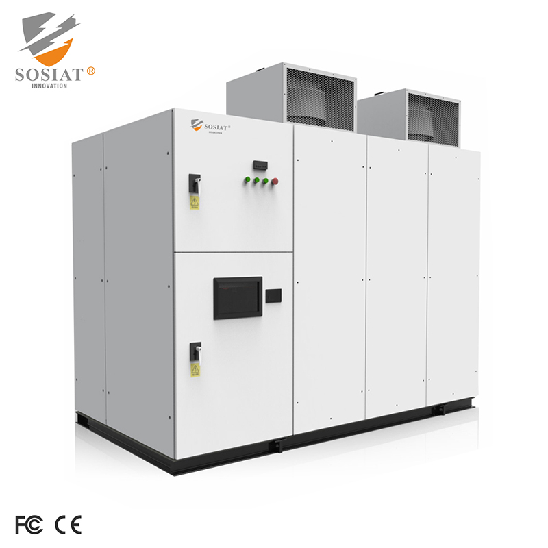


Medium and high voltage Ac motorsolid-state soft starter cabinets
Application Industry

Features
1. A digital microprocessoris used to manage data and communication. Signal grading processing and isolation technology are adopted, enabling the system to have
strong anti-interference ability. Moreover, the equipment control is real-time and efficient, with good stability and high reliability.
2. Advanced optical fiber transmission control technology is used to trigger high-voltage thyristors.
3. Safe isolation between the detection and high-low voltage control circuits ensures high safety.
4. High-frequency power supply isolation and transformation technology are used to provide a safe and reliable working power supply for electronic devices
operating in the high-voltage part.
5. The static and dynamic voltage equalization and absorption technology of the resistance-capacitance networkensures the reliable and safe operation of power
devices in series under high voltage.
6. The electronic EVT(Electronic Voltage Transformer) technology is adopted. Electronic sampling and optical fìber transmission are free from interference and
phase shift.
7. Starting curves are designed to adapt to the mechanical characteristics and requirements of different motor systems. The motor torque is automatically adjusted
to obtain a smooth acceleration curve and reduce electrical and mechanical shocks during the starting process.
8. Stopping curves are provided to adapt to the mechanical characteristics of different loads. There is a function of adjustable final torque , which effectively prevents
the water hammer effect caused by the shutdown of pump-type loads.
9. The pulse jump function improves the initial starting torque and is suitable for high-static-resistance torque systems.
10. Protection functions: There are over-voltage, under-voltage, multiple overload protection curves, as well as under-current, phase loss, phase imbalance, wrong phase sequence, zero-sequence grounding protection, thyristor over-temperature, excessive starting time, starting interval limitation, thyristor failure protection, etc.
11. The V-DN series high-voltage solid - state soft starters can use a low-voltage (380V) motor for simulation debugging before on-site high-voltage operation,
providing technical data and guarantees for formal operation.
12. The cabinet adopts the KYN28A-12 structure type. The materials are imported aluminum-zinc - coated steel plates, which have the advantages of corrosion resistance, oxidation resistance, novel and beautiful appearance, and high protection level . It can also be conveniently combined with the KYN28A-12standard middle-installed cabinet.
13. The speed feedback control function: Foroccasions requiring linear acceleration and deceleration, a speed feedfeedback unit can be optionally connected to obtain
the linear acceleration and deceleration characteristics of the motor.(Optional)
14. For the occasion of generator-powered motors, a special control program is set to ensure successful starting under unstable voltage, current, and frequency conditions. With appropriate reactive power compensation,a lightly-loaded motor can be successfully started when the generator capacity is more than1.35 times the apparent power of the motor.
15. Parameter adjustment function: For two-speed motors, or in the case of power supply from the power grid/ generator, or when the parameters of two motors are
different in a one-drag-two situation,
16. Two sets of starting and stopping parameters can be input. The required set of parameters can be conveniently selected through programmable terminals for
starting and operation.
17. It has a friendly human-machine operation inteface and historical data statistical query function. If necessary, a touch-screen interface can be optionally
selected to better realize human-machine information exchange.
18. It has an RS485 interface, and communication protocols (Modbus/ Profibus) are optional, which is convenient for users to achieve centralized monitoring.
19. Insulation detection function.(Optional)
Performance Parameters
1. Control mode: Pulse jump starting, voltage ramp, constant current, speed control (optional)
2. Starting method: Soft start, direct start, soft stop, free stop.
3. Operation mode: Control on the cabinet, external control, communication remote control(optional)
4. Communication method:RS485 interface; Modbus protocol and Profibus protocol(optional)
5. Analog output: Motor operating current, with the signal being 0-10V or 4-20mA or 0-20mA.
6. Initial voltage:10%~50% Un(can be extended to 5%~80% Un)
7. Current limiting multiple:100%~400% In(can be extended to 500% In)
8. Starting and stopping time:1~30S(can be extended to 90S)
9. Starting pulse jump: Current,70%-700% In (when the pulse jump time is 0~10 seconds)
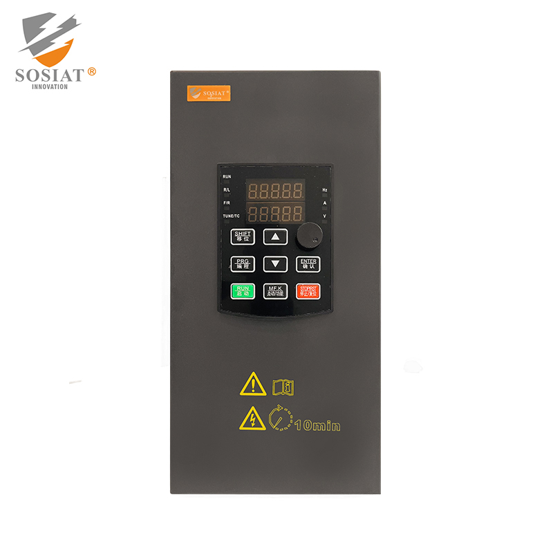
10. Parameter setting:1--Control panel buttons;2--Background communication setting.
11. Liquid crystal display: Parameters such as working current, number of starts, running time, and fault information, etc. Default languages: Chinese(English), German, French, Spanish.
12. Noise level:<80dB
13. Continuous starting interval: When the ambient temperature is higher than 40°C and the starting current is greater than 400% In, the interval should not be less than 30 minutes. When the temperature is relatively low and the starting current is relatively small, the interval can be appropriately reduced, but it should be at least 15 minutes.
14. Cooling method: Natural cooling.
15. Operation power supply:AC220V/50Hz600VA(Special requirements need to be specified separately)
16. Power frequency withstand voltage of the main circuit:42KV/1minute (excluding the power unit)
17. Protection mode: Composite (See the introduction of protection functions)
18. Protection level:IP42(IP54 can be selected for special requirements)
Working Environment
Operating temperature of the ambient air around the equipment:-10℃ to 50°C.
Storage temperature:-20℃ to 70℃(Special conditions should be declared when placing an order).
The relative humidity of the ambient air around the equipment should not exceed 95% at+50°C. A higher relative humidity is allowed at lower temperatures.
There should be no explosion-hazard and corrosive gases in the surrounding environment of the equipment. Pollution degree:≤3(can be increased to 4).
Vibration: The allowable vibration conditions at the installation site are as follows: the vibration frequency ranges from 10 Hz to 150 Hz, and the vibration acceleration is not more than 0.5m/s².
Main circuit power supply: Three-phase,10kV/50 Hz. The continuous voltage fluctuation should not exceed-15% to +10%.
The frequency fluctuation should not exceed ±5 Hz, and the frequency change rate should not exceed±1% per second.
Altitude:≤1000 m(can be extended to 4000 m).
Remarks: The parts in black font in the performance, parameters, working environment and conditions are standard configurations. If the user has other requirements for the text within the brackets,they should be clearly specified in the contract or technical agreement when placing an order!
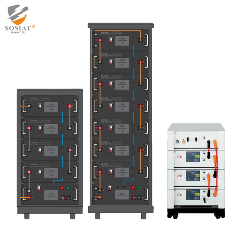
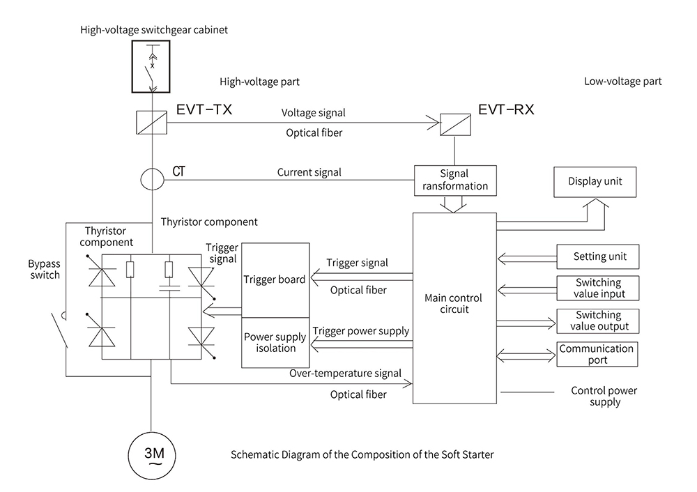
Components of the soft starter
High-voltage part: The high-voltage devices in the high-voltage compartment mainly include high-voltage thyristor components,EVT-TX (voltage signal transmitter), current transformers, trigger boards, bypass switches, etc.
Low-voltage part: The low-voltage devices in the low-voltage compartment mainly include the main control circuit,EVT-RX (voltage signal receiver), signal converters, setting units, input and output units, power supplies, etc.
Model Selection
The products with a voltage level of 3.3kv can be used to replace those with a voltage level of2.3k;the products with a voltage level of6.0kv can beused to replacethose with a voltage level of 4.16KV and 6.6KV.
The soft starter must be selected accordine to the rated currentindicated on the motor nameplate leven ifthe motor is not operatine atfiuload. The corespondineKW values given in the table are for reference only,. However, it should be noted that when the motor powers at iferent voltage levels arethe same,the curents aredifferent, When selecting the model, please calculate the current according to the power and then confirm.
| Model | Voltage (KV) | Current (A) | Power (kW) | Size W*D*H (mm) |
| SHMV-DN-03-60 | 3 | 60 | 265 | 1000*1300 (1500) *2300 |
| SHMV-DN-03-100 | 3 | 100 | 442 | 1000*1300 (1500) *2300 |
| SHMV-DN-03-200 | 3 | 200 | 883 | 1000*1300 (1500) *2300 |
| SHMV-DN-03-300 | 3 | 300 | 1325 | 1000*1300 (1500) *2300 |
| SHMV-DN-03-400 | 3 | 400 | 1767 | 1000*1300 (1500) *2300 |
| SHMV-DN-03-600 | 3 | 600 | 2650 | 2500*1660*2400(Subject to actual situation) |
| SHMV-DN-03-800 | 3 | 800 | 3533 | 2500*1660*2400(Subject to actual situation) |
| SHMV-DN-03-1000 | 3 | 1000 | 4417 | 3250*1660*2400(Subject to actual situation) |
| SHMV-DN-03-1200 | 3 | 1200 | 5300 | 3250*1660*2400(Subject to actual situation) |
| SHMV-DN-03-1400 | 3 | 1400 | 6183 | 3250*1660*2400(Subject to actual situation) |
| SHMV-DN-06-60 | 6 | 60 | 530 | 1000*1300 (1500)*2300 |
| SHMV-DN-06-100 | 6 | 100 | 883 | 1000*1300 (1500)*2300 |
| SHMV-DN-06-200 | 6 | 200 | 1767 | 1000*1300 (1500) *2300 |
| SHMV-DN-06-300 | 6 | 300 | 2650 | 1000*1300 (1500) *2300 |
| SHMV-DN-06-400 | 6 | 400 | 3533 | 1200*1300 (1500)*2300 |
| SHMV-DN-06-600 | 6 | 600 | 5300 | 2500*1660*2400(Subject to actual situation) |
| SHMV-DN-06-800 | 6 | 800 | 7067 | 2500*1660*2400(Subject to actual situation) |
| SHMV-DN-06-1000 | 6 | 1000 | 8833 | 3250*1660*2400(Subject to actual situation) |
| SHMV-DN-06-1200 | 6 | 1200 | 10600 | 3250*1660*2400(Subject to actual situation) |
| SHMV-DN-06-1400 | 6 | 1400 | 12366 | 3250*1660*2400(Subject to actual situation) |
| SHMV-DN-10-60 | 10 | 60 | 883 | 1000*1300(1500)*2300 |
| SHMV-DN-10-100 | 10 | 100 | 1472 | 1000*1300 (1500)*2300 |
| SHMV-DN-10-200 | 10 | 200 | 2944 | 1000*1300 (1500) *2300 |
| SHMV-DN-10-300 | 10 | 300 | 4417 | 1200*1300 (1500) *2300 |
| SHMV-DN-10-400 | 10 | 400 | 5889 | 1200*1300 (1500)*2300 |
| SHMV-DN-10-600 | 10 | 600 | 8833 | 2500*1660*2400(Subject to actual situation) |
| SHMV-DN-10-800 | 10 | 800 | 11778 | 2500*1660*2400(Subject to actual situation) |
| SHMV-DN-10-1000 | 10 | 1000 | 14722 | 3250*1660*2400(Subject to actual situation) |
| SHMV-DN-10-1200 | 10 | 1200 | 17666 | 3250*1660*2400(Subject to actual situation) |
| SHMV-DN-10-1400 | 10 | 1400 | 20611 | 3250*1660*2400(Subject to actual situation) |
| SHMV-DN-13.8-60 | 13.8 | 60 | 1219 | 1000*1660*2400(Subject to actual situation) |
| SHMV-DN-13.8-100 | 13.8 | 100 | 2032 | 1000*1660*2400(Subject to actual situation) |
| SHMV-DN-13.8-200 | 13.8 | 200 | 4063 | 1000*1660*2400(Subject to actual situation) |
| SHMV-DN-13.8-300 | 13.8 | 300 | 6095 | 1000*1660*2400(Subject to actual situation) |
| SHMV-DN-13.8-400 | 13.8 | 400 | 8127 | 1000*1660*2400(Subject to actual situation) |
| SHMV-DN-13.8-600 | 13.8 | 600 | 12190 | 2500*1660*2400(Subject to actual situation) |
| SHMV-DN-13.8-800 | 13.8 | 800 | 16253 | 2500*1660*2400(Subject to actual situation) |
| SHMV-DN-13.8-1000 | 13.8 | 1000 | 20316 | 3250*1660*2400(Subject to actual situation) |
| SHMV-DN-13.8-1200 | 13.8 | 1200 | 24380 | 3250*1660*2400(Subject to actual situation) |
| SHMV-DN-13.8-1400 | 13.8 | 1400 | 28443 | 3250*1660*2400(Subject to actual situation) |
Ordering Information:
Instructions Related to the Cabinet:
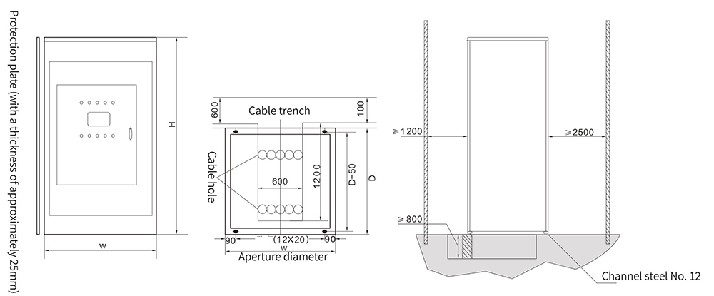
The main method ofcable inlet and outlet forthis product is botom-in and botom-out. Therefore,there should be a cable channel of suficient size under the foundationProtective plates can be added to both sides ofthe cabinet as required,with each side plate being25mm thick.(Pleae specilfy when placing an order ifneeded.This productundereoes a powder coating treatment on its surface, The default color is Computer Grey: MB2071 (RAL7032). (Please specify when placing an
order if there are special color requirements.)
By default, the opening direction of the front door of the low-voltage compartment is to the right.
Ifthere are other special requirements regarding the cabinet's form, dimensions, etc, we can customize, design, and manufacture it according tothe user's requests.
OrderingInformation and Examples:
Selecthe starter according to the rated curent ofthe motor andthe working mode, and wite down the complete productspecification and model as speciied bythe product mode.
When there are diferences from the standard configuration in the sample, please clearly state them separately in the contract (ortechnical agreement.
When placing an order, customers are required to providethe specficaton and mode! of the equiped motor,the main parameters,aswelasthe type and characteisics ofthe divenequipment.