


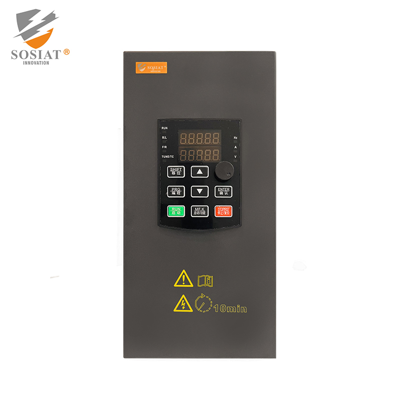
Variable Frequency Drive


0102030405
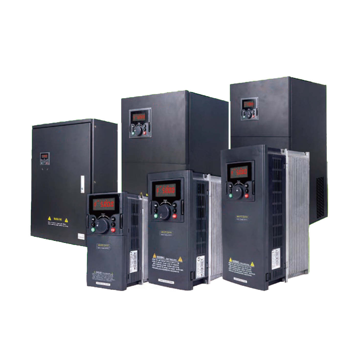
SHBFG Series Universal VectorAC Drive
Technical Features
- Support V/F control, open loop vector control, closed loop vector control of asynchronous andsynchronous motor control.
- VTC current vector control algorithm can reach to high start torque and low speed stable torque.
- HPVFD has combines the rich industrial application functions, so that it can realize all kinds of fieldcontrol requirements.
- To design,test and produce converters in strict accordance with international standard, it is designedbetter in heat dissipation carrying capacity and electromagnetic compatibility.
- lt provides Multi-functional 8 period of digital input, 2 road analog input , 2 road relay output and 2road open collector output.
- All this configuration is RS485 serial communication interface. Products are using the standardModbus communication protocol, and it is built-in input filter in 18.5-560KW.
- SHBFG series are provincial new products ,its functions of energy-saving operation and automaticcurrent limiting function can ensure normal operation.
- lt is convenient to handle by LED and LCD interface, meanwhile, it is easy to debug with panelparameter copy function.
- With flame retardant and high reliable main loop connection mode, all series products ensure itssafety.
Technical Specifications
| Model number |
Power (KW) |
Output Current(A) |
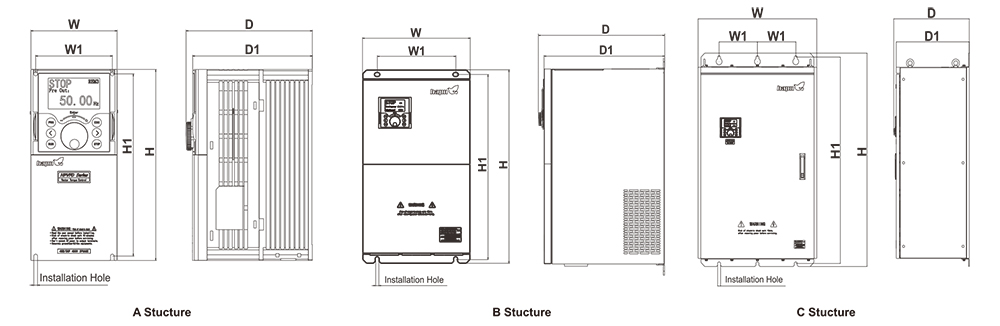
Inverter Frame |
W(mm) | H(mm) | D(mm | W1(mm) | H1(mm) | d(mm) |
| SHBFG60D75G21B | 0.75 | 3.8 | A | 105 | 160 | 137 | 94 | 150 | 4.5 |
| SHBFG601D5G21B | 1.5 | 7.0 | 105 | 216 | 157 | 94 | 206 | 4.5 | |
| SHBFG602D2G21A | 2.2 | 9.0 | |||||||
| SHBFG60D75G23B | 0.75 | 3.8 | A | 105 | 160 | 137 | 94 | 150 | 4.5 |
| SHBFG601D5G23B | 1.5 | 7.0 | 105 | 216 | 157 | 94 | 206 | 4.5 | |
| SHBFG602D2G23A | 2.2 | 9.0 | |||||||
| SHBFG604D0G23A | 4.0 | 13 | 126 | 260 | 183 | 110 | 246 | 6 | |
| SHBFG605D5G23A | 5.5 | 25 | |||||||
| SHBFG607D5G23A | 7.5 | 33 | 153 | 341 | 204 | 137 | 327 | 7 | |
| SHBFG60011G23A | 11 | 45 | |||||||
| SHBFG60015G23A | 15 | 60 | 180 | 423 | 204 | 120 | 420 | 9 | |
| SHBFG618D5G23A | 18.5 | 75 | |||||||
| SHBFG60022G23A | 22 | 91 | 191 | 471 | 242 | 120 | 450 | 9 | |
| SHBFG60D75G01D5P43B | 0.75/1.5 | 3.4/4.8 | A | 105 | 160 | 137 | 93.5 | 150 | 4.5 |
| SHBFG601D5G02D2P43B| | 1.5/2.2 | 4.8/6.2 | |||||||
| SHBFG602D2G04D0P43A | 2.2/4.0 | 6.2/11 | 105 | 216 | 157 | 93.5 | 206 | 4.5 | |
| SHBFG604D0G05D5P43A | 4.0/5.5 | 11/14 | |||||||
| SHBFG605D5G07D5P43A | 5.5/7.5 | 14/18 | 126 | 260 | 183 | 110 | 246 | 6 | |
| SHBFG607D5G0011P43A | 7.5/11 | 18/27 | |||||||
| SHBFG60011G0015P43A | 11/15 | 27/34 | 153 | 341 | 204 | 137 | 327 | 7 | |
| SHBFG60015G18D5P43A | 15/18.5 | 34/41 | |||||||
| SHBFG618D5G0022P43A | 18.5/22 | 41/52 | 180 | 423 | 204 | 120 | 420 | 9 | |
| SHBFG60022G0030P43A | 22/30 | 52/65 | |||||||
| SHBFG60030G0037P43A | 30/37 | 65/80 | 191 | 471 | 242 | 120 | 450 | 9 | |
| SHBFG60037G0045P43A | 37/45 | 80/96 | |||||||
| SHBFG60045G0055P43A | 45/55 | 96/128 | B | 300 | 541 | 314 | 220 | 516 | 11 |
| SHBFG60055G0075P43A | 55/75 | 128/165 | |||||||
| SHBFG60075G0090P43A | 75/90 | 165/185 | 350 | 730 | 354 | 270 | 705 | 11 | |
| SHBFG60090G0110P43A | 90/110 | 185/224 | |||||||
| SHBFG60110G0132P43A | 110/132 | 224/260 | |||||||
| SHBFG60132G0160P43A | 132/160 | 260/302 | C | 500 | 780 | 354 | 180 | 755 | 11 |
| SHBFG60160G0200P43A | 160/185 | 302/340 | 650 | 1060 | 414 | 210 | 1024 | 16 | |
| SHBFG60200G0220P43A | 200/220 | 380/450 | |||||||
| SHBFG60220G0250P43A | 220/250 | 450/480 | 750 | 1170 | 414 | 230 | 1128 | 18 | |
| SHBFG60250G0280P43A | 250/280 | 480/520 | |||||||
| SHBFG60280G0315P43A | 280/315 | 520/605 | |||||||
| SHBFG60315G0350P43A | 315/350 | 605/670 | 850 | 1280 | 464 | 275 | 1236 | 20 | |
| SHBFG60350G0400P43A | 350/400 | 670/750 | |||||||
| SHBFG60400G0450P43A | 400/450 | 750/810 | |||||||
| SHBFG60450G0500P43A | 450/500 | 810/860 | 1043 | 1426 | 464 | 250 | 1382 | 20 | |
| SHBFG60500G0560P43A | 500/560 | 860/990 | |||||||
| SHBFG60560G0600P43A | 560/630 | 990/1100 |
| Iterm | Specifications | ||
| Standard functions |
Maximum frequency | · Vector control:0-300 Hz ·V/F control:0-320 Hz |
|
| Carrier frequency | 1-16 kHz The carrier frequency is automatically adjusted based on the load | ||
| Input frequency resolution |
Digital setting:0.01 Hz Analog setting: maximum frequency ×0.025% |
||
| Control mode | · Sensorless flux vector control(SFVC) · Closed-loop vector control(CLVC) · Voltage/ Frequency(V/F) control |
||
| Startup torque | ·G type:0.5 Hz/150%(SFVC);0hZ/180%(CLVC ·P type:0.5 Hz/100% |
||
| Speed range | 1:100(SVC) | 1:1000(FVC) | |
| Speed stability accuracy |
±0.5%(SVC) | ±0.02%(FVC) | |
| Torque control accuracy |
±5%(FVC) | ||
| Overload capacity | ·G type:60s for 150% of the rated current, 3s for 180% ofthe rated current ·P type:60s for 120% of the rated current, 3s for 150% ofthe rated current |
||
| Torque boost | Custonized boost0.1%-30.0% | ||
| V/F curve | · Straight-line V/F curve · Multi-point V/F curve ·N-power V/F curve(1.2-power,1.4-power,1.6-power,1.8-power, square) |
||
| V/ Fseparation | Two types: complete separation; half separation | ||
| Ramp mode | · Straight-line ramp ·S-curve ramp Four groups of acceleration/ deceleration time with the range of 0.0-6500.0s |
||
| DC braking | DC braking frequency:0.00 Hz to maximum frequency; Braking time:0.0-600.0s; Braking action current value:0.0%-150.0% |
||
| JOG control | JOG frequency range:0.00-50.00 Hz;JOG acceleration/ deceleration time:0.0- 6500.0s |
||
| Onboard multiple preset speeds |
It implements up to 16 speeds via the simple PLC function or combination of DI |
||
| Onboard PID | It realizes process-controlled closed loop control system easily. | ||
| Auto voltage regulation(AVR) |
It can keep constant output voltage automatically when the mains voltage changes. | ||
*More details please reference to manual book
| Iterm | Specifications | |
| Overvoltage / Overcurrent stall control |
The current and voltage are limited automatically during the running process so as to avoid frequenttripping due to overvoltage/ overcurrent. |
|
| High-speed current limiting function |
Minimize over-current fault and protect normal operation of AC drive. | |
| Torque limit and control |
It can limit the torque automatically and prevent frequent over current tripping during the running process. Torque control can be implemented in the CLVC mode. |
|
| Individualiz ed functions |
High performance | Control of asynchronous motor and synchronous motor are implemented through the high-performance current vector control technology. |
| Power dip ride through |
The load feedback energy compensates the voltage reduction so that the AC drive can continue to run for a chort time. |
|
| Rapid current limit | It helps to avoid frequent overcurrent faults of the AC drive. | |
| Timing control | Time range:0.0-6500.0 minutes | |
| Multiple communication protocois |
It supports communication via Modbus-RTU,PROFIBUSDP,CANlink and CANoper | |
| Motor overheat protection |
The optional I/O extension card enabies AI4 to receive the motor temperature sensor input(PT100,PT1000) so as to realize motor overheat protection. |
|
| Multiple encoder types |
It supports various encoders such as differential encoder, open-collector encoder, resolver, UVW encoder, and SIN/COS encoder. |
|
| Advanced background |
It supports the operation of AC drive parameters and virtual oscillograph function, via which the state inside the AC drive is monitored. |
|
| RUN | Running command source |
· Operation panel · Control terminals · Serial communication port You can perform switchover between these sources in various ways. |
| Frequency source | There are a total of 10 frequency sources, such as digital setting, analog voltage setting, an alog current setting, pulse setting and serial communication port setting. You can perform switchover between these sources in various ways. |
|
| Auxiliary frequency source |
There are ten auxiliary frequency sources. It can implement fine tuning of auxiliary frequency and frequency synthesis. |
|
| Input terminal | Standard: 8 digital input(DI) terminals, one of which supports up to 50kHz high-speed pulse input 3 analog input(AI) terminals, two of which only supports 0-10V voltage input and the other supports 0-10 V voltage input or 0-20 mA current input |
|
| Output terminal | Standard: 1 high-speed pulse output terminal(open-collector) that supports 0-50 kHZ square wave signal output, 2 digital output(DO) terminal,2 relay output terminal, 2 analog output(AO) terminal that supports 0-20 mA current output or 0-10 V voltage output |
|
*More details please reference to manual book
| Iterm | Specifications | |
| Display and operation the operation panel |
LED display | It displays the parameters |
| LCD display | Optional, Chinese/ English prompt operation content | |
| Parameters copy | Quick copying of parameters can be realized through LCD operation panel option. | |
| Key locking and function selection |
It can lock the keys partially at power-on, input/ output phase loss protection, overcurrent protection, overvoltage protection, undervoltage protection, overheat protection and overload protection |
|
| Protection mode |
Protection mode | Moto r short-circuit detection at power-on, input/ output phase loss protection, overcurrent protection, overvoltage protection, undervoltage protection, overheat protection and overload protection |
| Optional parts |
Optional parts | LCD operation panel, braking unti, I/O extension card 1, I/O extension card 2, user programmable card, RS485 communication card,PROFIBUS-DP communication card, CANink communication card,CANopen communication card, differential input PG card, UVW differential input PG card, resolver PG card and OC input PG card |
| Enviroment | Installation location | Indoor, free from direct sunlight, dust, corrosive gas, combustible gas, oil smoke, vapour, drip or salt. |
| Altitude | Lower than 1000m | |
| Ambient | Minus 10℃ to+40℃ (derated if the ambient temperature is between 40℃ and 50°) | |
| Humidity | Less than 95%RH, without condensing | |
| Vibration | Less than 5.9m/s(0.6g) | |
| Storage | Minus 20℃~+60℃ | |
| IP level | IP20 | |
| Pollution degree | PD2 | |
*More details please reference to manual book